Hardwiring a Dashcam in a Vehicle
A few weeks ago, I purchased a dashcam, because why not? Driving more frequently, I thought I’d get something to be able to record my commute in the event where I’m involved in an accident. And with the amount of bad drivers in Michigan I’m surprised I haven’t done this earlier…anyways, I got tired of having to use my cigarette lighter to power it on, as my vehicle’s socket is always on, requiring me to have to disconnect and reconnect the cable every darn time. Instead, I decided to tinker with the available fuses in my car’s instrumentation panel, to tap into a circuit that is only enabled upon ignition, or when the engine is on.
Step 1 - What’s Needed
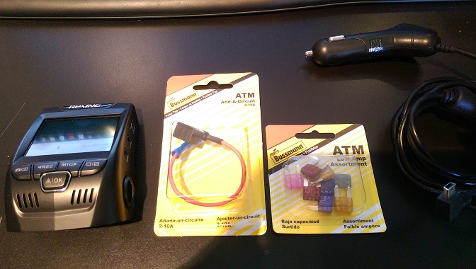
- I will be using a moderately priced dashcam, the Rexing V1.
- An Add-A-Circuit, to piggy back our circuit from an existing socket in the fuse box. This is a clean way of hardwiring, rather than just adding a wire into a fuse- a much messier and less safe approach.
- A fuse, with appropriate amperage rating. 2-3 amps should do the trick.
- Some method of stepping down the ~12 volts from the power to the appropriate rating on your dashcam. For mine, I needed 5V. I had some voltage regulators laying around so I used that, along with the mini USB cable that was included with my dashcam, which will require a modification.
This should cost you less than $10, save the cost of the dashcam itself.
Step 2 - Wiring the Circuit
My power cable was not detachable from the cigarette lighter connector, so I snipped it off, as I wouldn’t need it from now on. To be safe, I made sure 5 volts is what I truly needed, so I measured the output of the connector when plugged in– and to confirm which wire was power and ground:
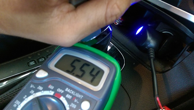
5.5 volts, good enough. For my voltage step-down circuit I will be using the L7805CV, a very common 5V voltage regulator:

Basically, I set up the wires so that the cable running from the Add-A-Circuit goes to the input to the L7805CV. Ground pin will go to both the negative pin of the USB cable (black), and to the bare metal chassis of my car. The last pin is the regulated 5 volt output, which goes to the power pin of the USB cable. I also threw in a 10 uF capacitor to stabilize the input to the regulator by connecting it to the input and ground pin. This required a bit of soldering and taping.
Step 3 - Connecting the Circuit
Next step would be finding a good fuse to piggy back your circuit off of. What you do is you first bust out your multimeter, and look for points that are only on when your engine is running or is keyed-on. You can confirm this by measuring for voltage when the car is off, and when the car is on. Also important to note is that you need to find what side of the fuse is being supplied power to– which again is found easily by measure both sides and confirming there is voltage.
Once this is done, remove the original fuse and attach it to the bottom slot of the Add-A-Circuit. The top slot is where the new fuse goes. Then attach it, and voila! Ready to test.
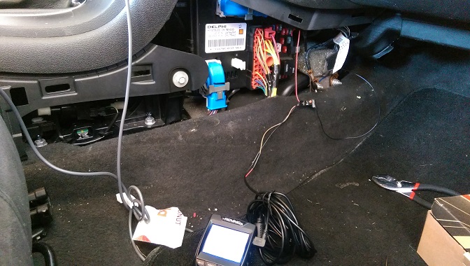
Don’t worry, I cleaned it up a bit after that image…this allows me to better hide the cables and avoid manually plugging and unplugging it! More details about how I wired everything will be added soon.